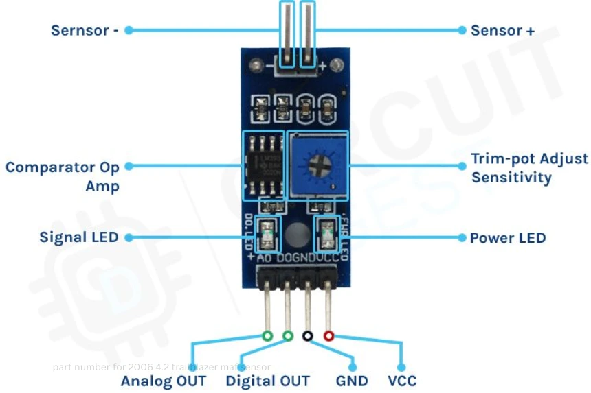
In the realm of electronics and embedded systems, interfacing different components seamlessly is crucial for ensuring accurate data acquisition and system reliability. One common challenge faced by hobbyists and professionals alike is the integration of a 3.3V sensor into a 5V Analog-to-Digital Converter (ADC) system. This guide will delve into the details of how to connect a 3.3V sensor into a 5V ADC, ensuring optimal performance, safety, and accuracy.
Understanding the Voltage Levels: Why the Difference Matters
Before exploring the solutions, it’s essential to understand why the different voltage levels present a challenge. Many modern sensors operate at 3.3V logic levels due to their lower power consumption and compatibility with newer microcontrollers, such as ARM Cortex-M or ESP8266/ESP32 chips. Conversely, traditional ADC modules, especially older or more straightforward designs, often accept input voltages up to 5V.
The key concern when connecting a 3.3V sensor to a 5V ADC is whether the sensor’s output voltage stays within the ADC’s acceptable input range.ADC damage or erroneous readings may result from exceeding this range. Conversely, if the sensor’s output voltage is too low, the ADC might not interpret it correctly, especially if thresholds are not well-defined.
The Challenges of Direct Connection
Connecting a 3.3V sensor directly into a 5V ADC input may seem straightforward, but it involves some considerations:
Voltage Compatibility: The sensor outputs 3.3V for logic HIGH, which is generally within the ADC’s acceptable range, but if the ADC expects signals closer to 5V, the 3.3V signal might be too weak or interpreted as a LOW.
Signal Integrity: Minor voltage differences might result in unreliable readings, especially if the ADC’s threshold levels are not compatible with 3.3V signals.
Potential Damage: Though most 5V ADC inputs can tolerate 3.3V signals, if the sensor outputs a voltage higher than 3.3V (such as 5V for certain sensors), it can damage a 3.3V microcontroller or sensor.
To bridge this gap safely and accurately, voltage level shifting techniques are employed.
Voltage Level Shifting Techniques
To reliably connect a 3.3V sensor into a 5V ADC, you need to either step up the sensor’s output voltage in a controlled way or ensure the ADC interprets 3.3V signals as high. The following methods are highly effective:
1. Use a Voltage Divider
The simplest and most economical method is a voltage divider.By using two resistors, you can scale down the 5V or higher signals to 3.3V compatible levels, or vice versa. For connecting a 3.3V sensor to a 5V ADC, usually, the sensor output can be fed directly, but to prevent any over-voltage if the sensor sometimes outputs higher voltages, a voltage divider ensures safety.
Example configuration:
R1 = 1kΩ
R2 = 2kΩ
The output voltage across R2 will be:
$$V_{out} = V_{in} \times \frac{R_2}{R_1 + R_2}$$
Choosing resistor values ensures that any incoming voltage beyond 3.3V is reduced to a safe level compatible with the ADC.
2. Use a Level Shifter or Level Translator
For more precise and bi-directional conversion, a dedicated level shifter IC can be used. These modules reliably translate signals bidirectionally, are fast, and maintain signal integrity.
3. Use a Buffer or Op-Amp Based Level Translator
Operational amplifiers can be configured as voltage followers with a specific reference voltage to shift and scale signals precisely. This is especially useful if the sensor’s output voltage varies significantly.
How to Connect a 3.3V Sensor to a 5V ADC Correctly
Here’s a practical step-by-step approach:
Identify the Sensor’s Output Specifications: Confirm whether the sensor’s output voltage is indeed 3.3V or if it might sometimes output higher voltages.
Assess the ADC Input Range: Check the ADC’s datasheet to confirm its acceptable input voltage levels and maximum ratings.
Choose a Level Shifting Technique: Decide whether a resistor voltage divider, level shifter, or op-amp is best suited to your project.
Design the Level Shifter Circuit: For example, if using resistors:
Calculate resistor values to ensure a 3.3V maximum output is within the ADC’s input range.
Connect the sensor’s output to the voltage divider’s input.
Attach the ADC input to the voltage divider’s output.
Test the Circuit Before Actual Use: Use a multimeter or oscilloscope to verify the voltage at the ADC input with different sensor outputs.
Connect to the Microcontroller or Data Logger: Once verified, connect the circuit and start collecting data.
Considerations and Best Practices
Input Impedance: Ensure the voltage divider or buffer does not overly load the sensor, affecting its output.
Filtering: Use small capacitors if necessary to filter noise and stabilize readings.
Ground Reference: Make sure all components share a common ground for accurate voltage referencing.
Calibration: Calibrate your ADC readings to account for any residual voltage drops or inaccuracies.
Conclusion
Connecting a 3.3V sensor into a 5V ADC system requires thoughtful planning and proper implementation to ensure reliable and safe operation. Utilizing voltage dividers, level shifters, or buffer amplifiers can bridge the voltage gap effectively, safeguarding components and ensuring accurate data collection. With these techniques, you can seamlessly integrate modern low-voltage sensors with traditional 5V ADC systems, enabling versatile and robust embedded projects.


